The EPROM Emulator, presented here by Keith Rickard, can be used with the Z88 to make developing ROM-based applications easier.
The Eprom emulator is a device which is connected to the parallel port of your PC (or Amiga) and allows you to send a Z88 Eprom image from a file to the emulator, using the DOS command: COPY filename LPT1:/B
The other end of the emulator is connected to a special card which is plugged into a slot in the Z88. The upshot is that the Z88 thinks it has a bona fide Eprom card in its slot and reacts to the image in the normal way. It could be an application or simply a file Eprom.
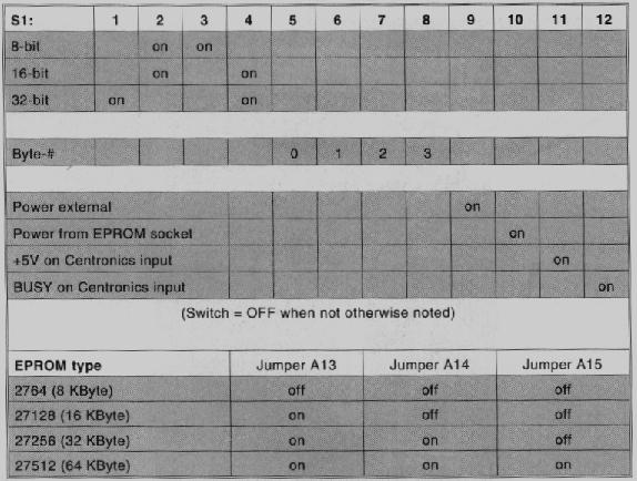
It can emulate 8K (not that useful!), 16K, 32K and 64K Eprom cards. It takes about 5 seconds for the image to be download from the PC. Obvious uses for this device (as deployed by myself) are improved ease for developing Z88 applications, downloading files to the Z88 and looking at other peoples application ROM images (have had Manic Miner and Camelot working through it!).
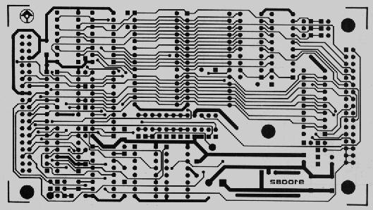
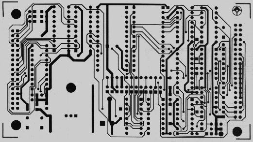
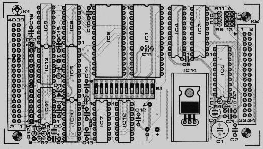
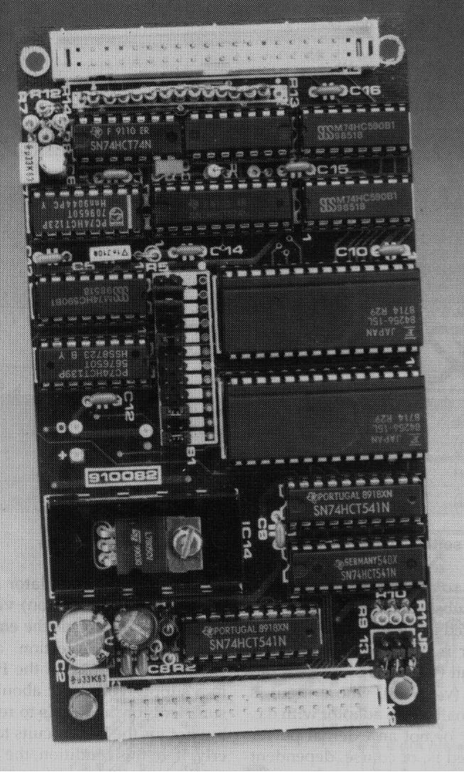
The design and construction of the emulator can be found in the following text file and images. If you prefer, a ZIP file of the entire lot can be downloaded for offline reading (approx 1Mb)
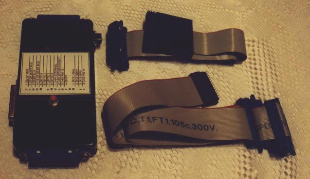
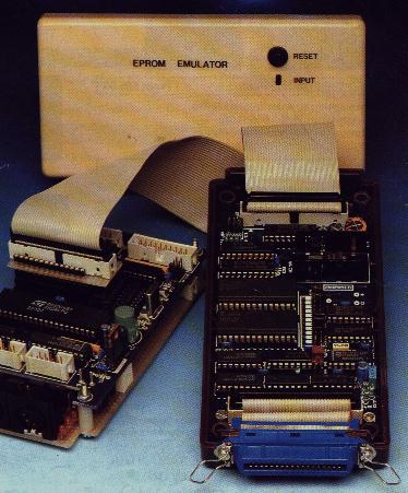
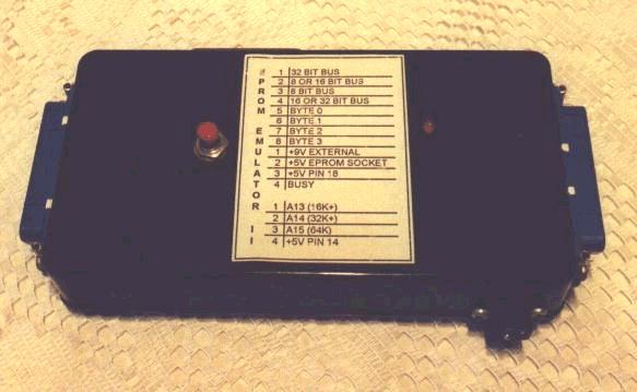
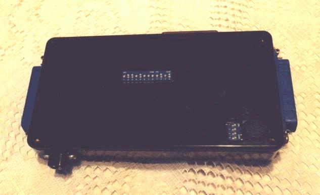
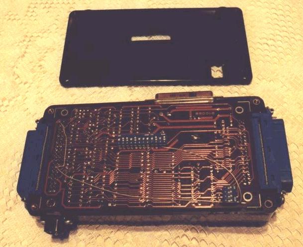
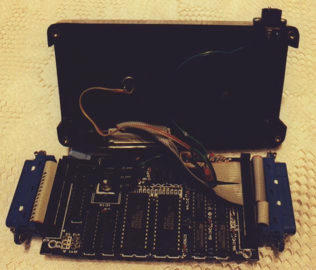
The following are pictures of Keith's own EPROM emulator:
Firstly the 32K RAM card needs to be prised apart (ouch!) in order to get access to the enclosed PCB. To do this proceed as follows:
You may, as I did, break a pin whilst doing this (oops- perhaps I should have mentioned this earlier!), but so long as you have two pins intact you will be okay.
Remove the lid to expose the PCB. The PCB can now be removed by gently lifting it up and over the pins. Remove all the components on the board. Do this by using a soldering iron to melt the solder and a de-soldering tool to remove it. Try to keep the soldering iron in contact with the solder for as little time as possible.
Next, take a 28 way IDC flat cable and 28 way DIL header. Slide the cable into the header ensuring that the cable sits in the slots neatly. Also ensure that the coloured edge line goes to pin 1 of where the RAM chip was originally. Slide the cable in up to the end of the slit. Place the header into a vice's jaws. The pin side will probably need packing between the base of the header and the vice jaw. Close the vice jaws slowly until the header lid clicks into place and the cable is stripped inside. Trim off the excess cable coming out of the header so it is flush.
Identify the connector no. 22 (WEL) on the card (the connectors are number from 1 to 38 from right to left - count both ends to ensure the correct track has been located) and cut the line carefully and cleanly with a sharp knife. Also cut the A14 line (connector no.18). These tracks serve no purpose.
Solder the header onto the PCB with the IDC cable falling away from the edge connector. Solder a small wire to the A15 track (connector no. 2), on the unbroken side, with the other end to pin 1 of the header. Similarly, solder a small wire to the A14 track (connector no. 18) to pin 27 on the header. I used wire-wrapping wire for this.
Next file the bottom edge of the PC to a depth equivalent to that of the IDC cable thickness. Also file the top of the back part of the card case to the same depth. The PCB should now be able to be placed comfortably back into the card case.
Once you're happy with your work re-assemble the card, clicking the lid on over the pins. Take the soldering iron and place it on each of the pins and melt them so that the lid will not come off. Be aware that unpleasant fumes will be let off. If you broke any pins it may be advisable, as I did, to glue around the edge before using the iron.
The card adapter is now complete - easy, eh? Let me know how you get on with the above.
Keith Rickard