Servicing Sinclair Computers Part 6 Previous instalments in this series have dealt with versions of the Spectrum up to and including the 3B. Development continued, and issues 4A, 4B, 5 and 6A subsequently appeared. With each new version the board varies somewhat from the previous one. The differences with the later versions are highlighted below. We'll deal with the voltage generator section separately because although the basic design remained the same there were a number of modifications.
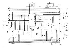
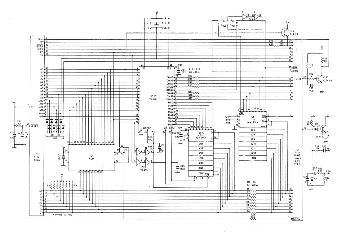
The Later Spectrums The issue 4A and 4B boards a re similar to the 3B, the main exception being the use of a 6C001-7 ULA chip. This necessitated a timing modification. The two spare nand gates in IC24 are connected in series (to maintain the correct polarity) and replace R32 in the RAS line to IC3 and 1 C4 (see Fig. 1 part 3). Replacement ULAs must be of the -7 or later type. A major change was introduced with the issue 5 board. The six decoder/multiplexer chips IC3, IC4, IC23, IC24, IC25 and IC26 were replaced with a Mullard ULA type ZX8401. But something seems to have gone wrong somewhere because the two gates are still needed in the RAS Line and the new circuit requires an additional four. A 74LS04 hex inverter chip (IC28) provides the six inverters required. Although these changes greatly altered the appearance of the board the basic circuitry hasn't changed very much and servicing shouldn't be affected. The issue 6 version is very similar to the issue 5 but there's now an alternative supplier of the main ULA (IC1) - Saga joins Ferranti. Certain component changes go with this (see Table 4). Fig. 12 shows the computing circuitry used in the issue 6 version - refer to Fig. 5 for the rest of the circuit. Note that for clarity some supply line decouplers have been omitted, also the connections to the edge connector (refer to Table 3 for these) The Voltage Generator Circuit
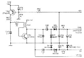
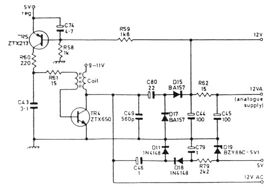
Throughout the development of the Spectrum circuit that's been most subject to change has been the voltage generator. The issue 3/3B version shown in Fig. 4 had already been substantially modified from the issue 1 version. The item that's seen most alteration has been R60, whose value has gone up and down in an almost random manner. Some of the changes are more logical. For example the introduction of the 22uF capacitor (C80) in the 12V supply: this isolates the 9-11V input from the output when there's an oscillator fault. It seems that each time the board was changed this circuit was subject to modification whether or not it improved the performance. In the hope that they got it right by this stage the issue 6 circuit is shown in Fig. 13 (lucky for some?). If you are making any changes I would recommend that you use the values shown here, though if you compare this circuit with Fig. 3 you'll see that they differ in only a few respects. In any case, when TR4 has blown the minimum alteration I'd advise would be to change R60 to 220ohm and to fit C80 and D17 if these are not already present. Any other changes are up to you. Correction Note that the EAR socket circuit was shown incorrectly in Fig. 5. It should be as shown in Fig. 12 in all versions. Alternative Components Instructions for fitting alternative ROM and ULA chips have been given in earlier instalments. RAM chip replacements have also been dealt with. It's recommended that all replacement ceramic capacitors are of the axial type - if you can get them. Here's a list of alternatives to the E-line transistors (you may find that some are more obscure than the originals): Table 4: Component changes when alternative ULAs are fitted to issue 8 boards.
.
|
||||||||||||||||||||||||||||||||||||||||||||||||||||||||||||||||||||
| [ Main Page ] [ Features ] |